Note. The Lumped and Full winding models described in this article apply to MotorXP-AFM 2.0 and later. In earlier versions the winding representation options differ.
Introduction #
The Lumped and Full winding parameters define how the conductors inside a stator slot are represented when the geometry is generated. This single choice drives model complexity, computational cost, and which physical effects you can actually capture.
Lumped winding model (equivalent model) #
All conductors in the slot are represented as a single equivalent object that fills the entire slot (see Figure 1.1). The visual shape of this object cannot be edited.
Use the Lumped model when there is no need to model each conductor as a separate geometric entity for simulation or analysis. This approach simplifies the geometry and lowers computational cost.
click on image to enlarge
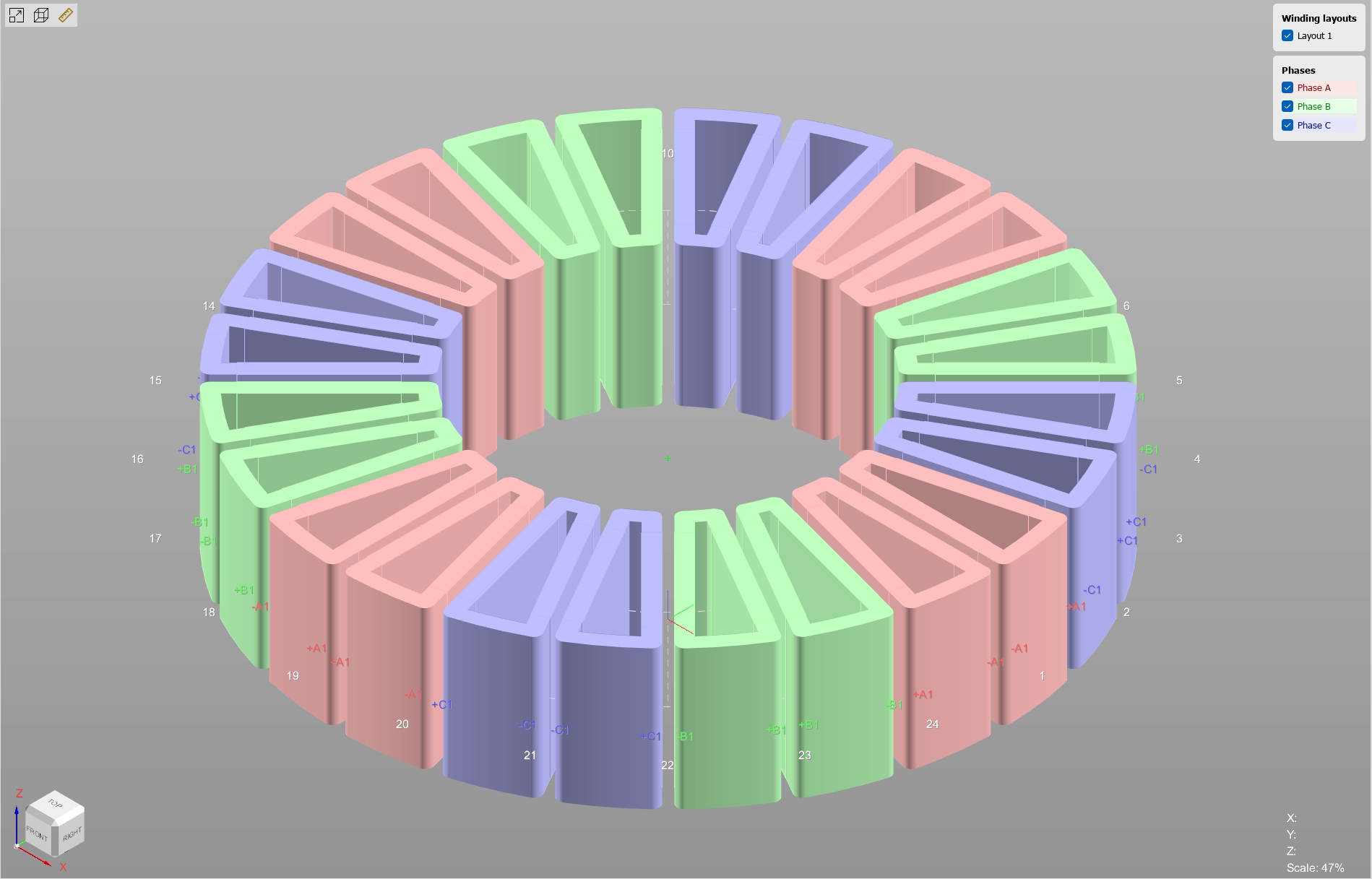
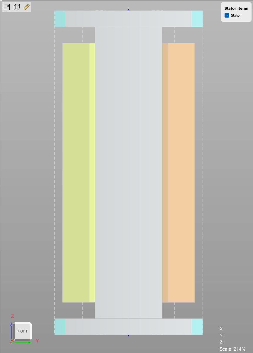
Figure 1.1. Lumped winding model: Winding Editor view (left) and Stator Editor view (right). The slot is rendered as a single equivalent body.
Full winding model (detailed model) #
Each individual conductor is modeled as an independent object, so its shape, dimensions, and exact position inside the slot can be configured individually (see Figure 1.2).
Use the Full model when the exact physical layout must be preserved. It lets you visualize the real arrangement of turns, evaluate slot fill, and account for how conductor shape affects the geometry. The Full model is intended for studying eddy currents in the conductors, the skin effect, and the proximity effect.
click on image to enlarge
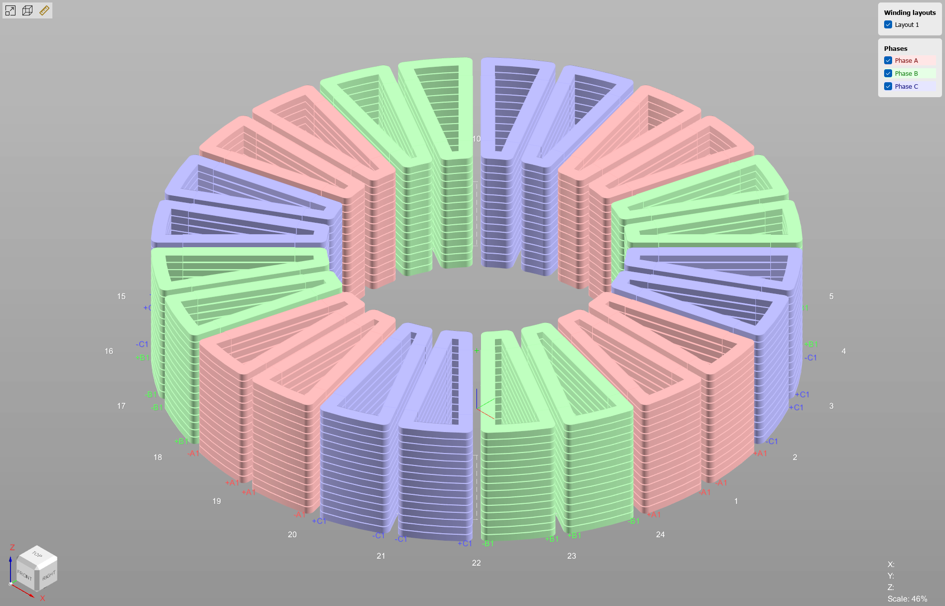
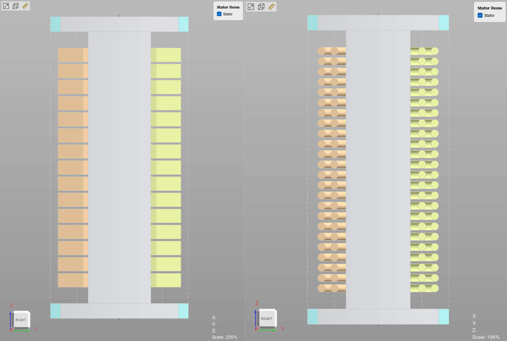
Figure 1.2. Full winding model: Winding Editor view (left) and Stator Editor view (right). The Stator Editor view shows both rectangular and round conductor cross-sections. Rectangular conductors can have rounded corners, while round conductors are arranged in a hexagonal packing.
Comparison of winding model parameters #
Figure 1.3 compares the Lumped and Full winding parameters for the same project (link to download the example below), and Table 1.1 summarizes the practical differences between the two representations. In Figure 1.3, pay attention to the end-winding inductance and phase resistance values.
click on image to enlarge
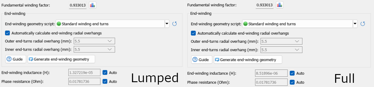
Figure 1.3. Winding parameters for the two conductor representations in the stator slot (Lumped on the left, Full on the right).
Note. For the Lumped model, the computed end-winding inductance is usually higher, because all turns are collapsed into a single filament.
Table 1.1. Lumped vs. Full winding model.
| Parameter | Lumped | Full |
| Conductor representation | One equivalent object filling the slot | Each conductor as an independent object |
| Shape & placement control | Not configurable | Per-conductor (shape, size, position) |
| Cross-section types | — | Round and rectangular |
| Computational cost | Low | High |
| Intended use | Fast, simplified analysis | Eddy currents, skin effect, proximity effect |
Download the example projects #
The figures and parameters above are taken from two ready-to-open MotorXP-AFM projects — one for each winding representation. Download them to reproduce the results:


