Note. The workflow described in this article applies to MotorXP-AFM 2.0 and later. In earlier versions the winding representation options and the analysis workflow differ.
Introduction #
The Lumped and Full winding parameters determine how the copper tracks are represented by the printed circuit board (PCB) stator geometry script. The selected representation affects the generated 3D geometry, model complexity, and the physical effects that can be resolved in a simulation.
Use the Lumped model for a simplified equivalent representation. Use the Full model when the individual PCB conductors and their actual arrangement must be included explicitly.
click on image to enlarge
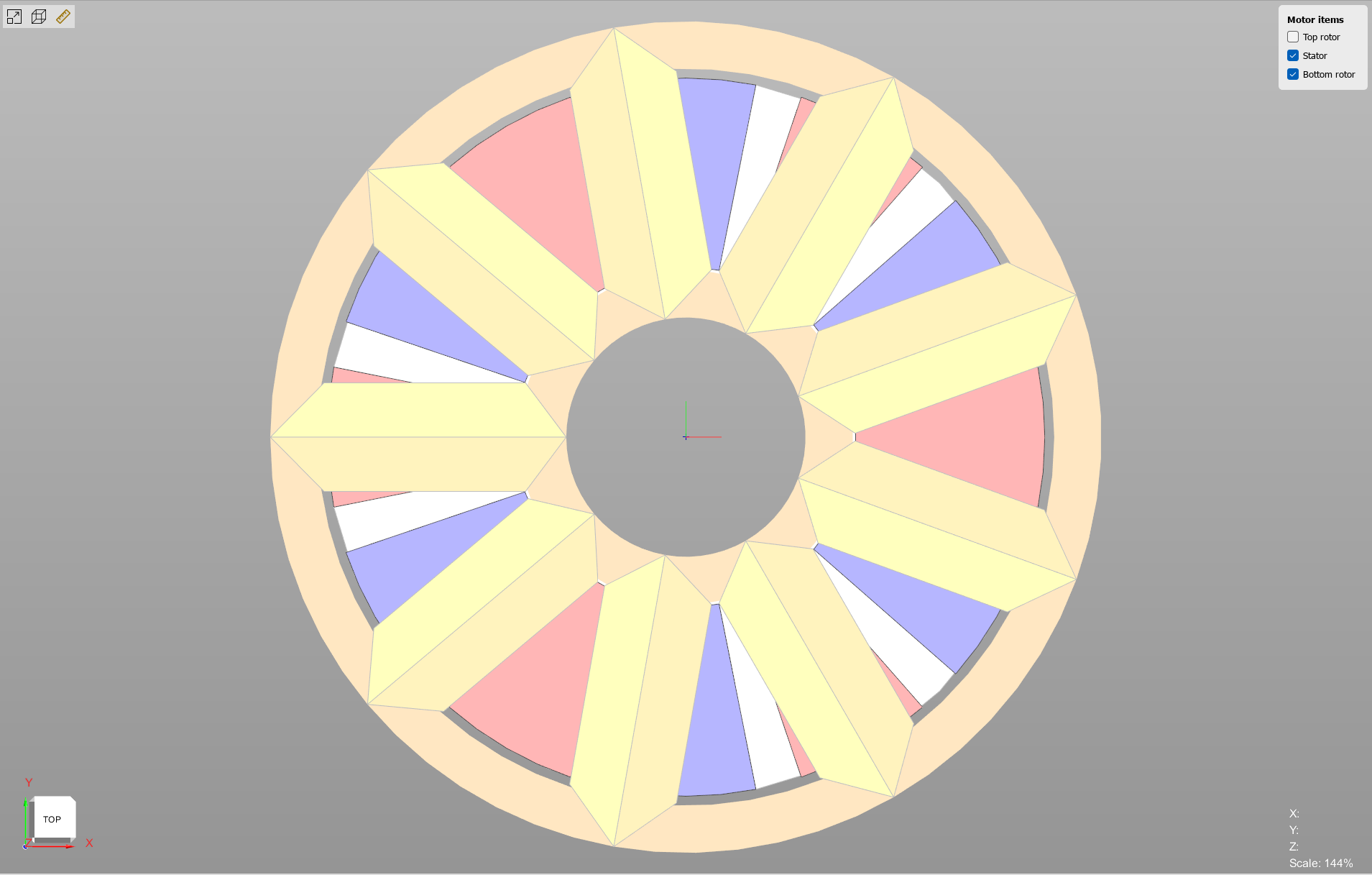
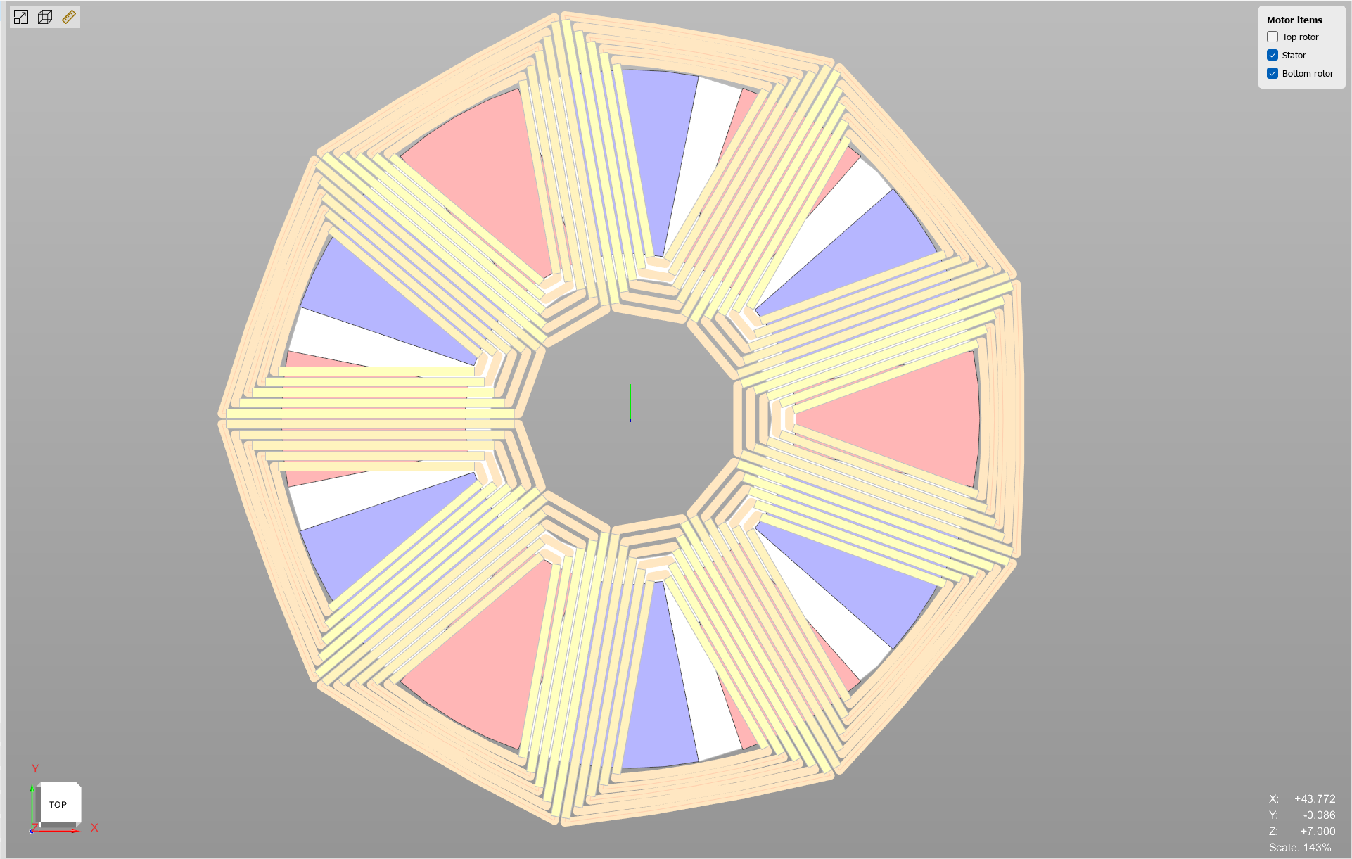
Figure 1.1. PCB stator winding geometry over the full stator: Lumped representation (left) and Full representation with individual tracks and layers (right).
Lumped and Full winding models #
In the Lumped model, all PCB turns are represented by one equivalent object that fills the available winding region. Individual tracks are not created as separate geometric objects, and the visual shape of the equivalent conductor cannot be edited. This representation keeps the geometry compact and significantly reduces computational cost.
In the Full model, each PCB conductor is generated as an independent object. The detailed representation preserves the physical track layout, makes the actual arrangement of turns visible, and allows conductor dimensions to affect the geometry. Use the Full model to study eddy currents, the skin effect, and the proximity effect.
click on image to enlarge
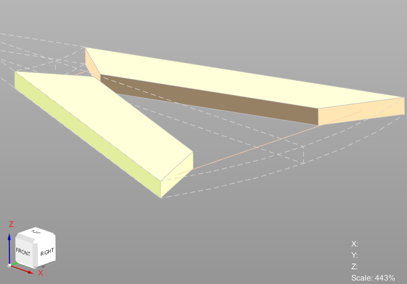
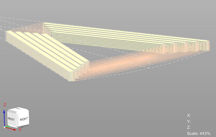
Figure 1.2. Close-up of a single PCB coil: Lumped representation (left) and Full representation with individual tracks and layers (right).
Supported topologies and required settings #
The PCB stator geometry script supports the Stator-Rotor (SR), Stator-Rotor-Stator (SRS), and Rotor-Stator-Rotor (RSR) topologies.
Table 1.1. Required winding and stator settings for the supported PCB topologies.
| Topology | Winding layers | Winding layer orientation | Stator type |
| SR | Double layer | Left/Right | Yoke |
| SRS | Double layer | Left/Right | Yoke |
| RSR | Double layer | Left/Right | Yokeless |
Note. In the Full model, the PCB geometry script supports rectangular conductors only.
Effect on winding parameters #
The conductor representation changes the winding geometry used by the project and can therefore change calculated winding parameters. Figure 1.3 shows the end-winding inductance and phase resistance for the same PCB stator project with the Lumped and Full representations.
click on image to enlarge
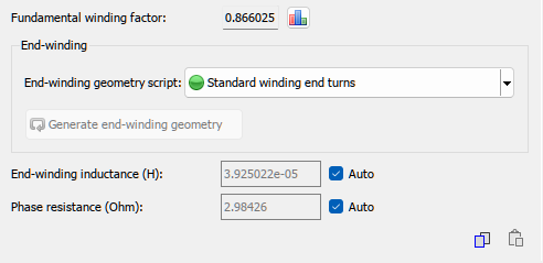
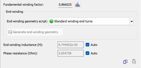
Figure 1.3. Winding parameters for the PCB stator project: Lumped model (left) and Full model (right).
PCB stator parameters in Geometry Editor #
The printed circuit board (PCB) stator geometry script provides the following parameters in Geometry Editor.
Table 1.2. PCB stator geometry parameters.
| Parameter | Description |
| PCB geometry | Selects the Lumped or Full geometric representation. |
| Number of turns per PCB layer | Number of coil turns on one conductive PCB layer. This value directly affects phase inductance and resistance. |
| Number of PCB layers | Total number of conductive layers used to implement the winding in the PCB stack. |
| Number of PCB layers connected in parallel | Number of PCB layers electrically connected in parallel to form one winding path. This affects current-carrying capability and AC resistance. |
| PCB surface utilization factor | Dimensionless factor from 0.01 to 1 that scales the active winding area relative to the available PCB surface. It accounts for manufacturing margins, clearances, and inactive routing regions. |
| Innermost coil turn length (mm) | Length of the innermost and shortest coil turn. It is the reference dimension used to construct the subsequent turns. |
| Conductor height (mm) | Copper track thickness in the vertical direction through the PCB stack. |
| Conductor width (mm) | Copper track width in the PCB layer plane. Together with conductor height, it defines the conductor cross-sectional area and DC resistance. |
| PCB-to-yoke gap (mm) | Air gap between the PCB winding and the magnetic yoke. It affects magnetic coupling, heat transfer, and assembly tolerances. |
| Yoke height (mm) | Height of the magnetic yoke surrounding the PCB stator. It affects the magnetic flux path and the saturation limit of the machine. |
Figure 1.4 shows the PCB stator parameter setup for two topology configurations: the Rotor-Stator-Rotor (RSR) motor configuration and the Stator-Rotor (SR) / Stator-Rotor-Stator (SRS) configuration.
click on image to enlarge
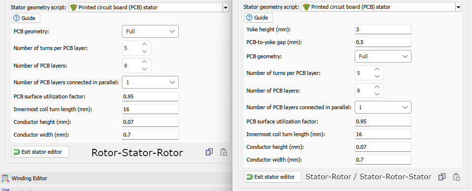
Figure 1.4. PCB stator geometry parameters with the Full representation selected for the RSR and SR/SRS configurations.
Which parameters affect the generated geometry #
In the Lumped winding model, all parameters can be edited, but only four of them change the generated 3D geometry: Yoke height, PCB-to-yoke gap, PCB surface utilization factor, and Innermost coil turn length.
In the Full winding model, the detailed conductor settings also become active in the 3D scene. These include Conductor width, Conductor height, Number of turns per PCB layer, and Number of PCB layers. Changing these values updates the visible arrangement and dimensions of the individual PCB tracks.
Generating the end-winding geometry #
After configuring the PCB stator parameters, click Generate end-winding geometry. Design Studio will create the 3D end-winding shapes and display them in the graphical scene.


