Note. This article describes the Winding Editor in MotorXP-AFM 2.0.
Before you start. See Winding Editor Overview for an introduction to the editor workspace and the recommended winding setup workflow.
Wire size method #
The Wire size method determines how the dimensions of one winding strand are specified. Depending on the selected method and conductor shape, the Winding Editor displays fields for strand diameter, width, height, corner radius, or wire gauge.
click on image to enlarge
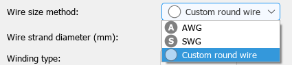
Figure 1. Wire size methods available for the current winding configuration.
MotorXP-AFM supports the following wire size methods:
| Method | Conductor definition | User input |
| Custom round wire | Round conductor with a custom strand diameter. | Enter the Wire strand diameter. |
| AWG | Round conductor sized according to the American Wire Gauge standard. | Select the required AWG number. The strand diameter is determined automatically. |
| SWG | Round conductor sized according to the Standard Wire Gauge. | Select the required SWG number. The strand diameter is determined automatically. |
| Rectangular wire | Conductor with a rectangular cross-section. | Enter the strand width, strand height, and strand corner radius. |
| Fill factor | Conductor definition based on the available winding area. | Specify either the Slot fill factor or the Coil fill factor. This method is available for the Lumped winding model. |
Conductor geometry examples #
Figure 2 shows how the selected wire size method and conductor dimensions affect the conductor arrangement in the slot.
click on image to enlarge
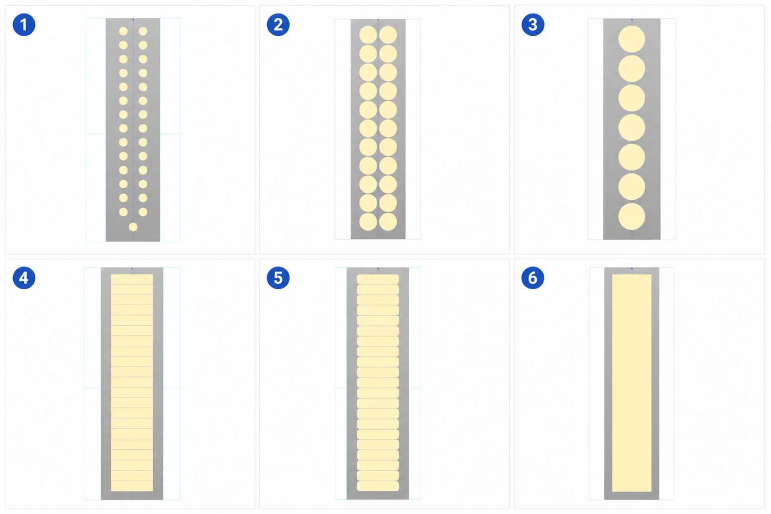
Figure 2. Conductor geometry examples for the available wire size methods.
- Custom round wire.
- AWG, with 8 AWG selected.
- SWG, with 6 SWG selected.
- Rectangular wire with square corners.
- Rectangular wire with rounded corners.
- Fill factor, available only for the Lumped winding model.
Round conductor dimensions #
For a round conductor, Wire strand diameter is the diameter of one individual strand. Enter the value directly when Custom round wire is selected, or select an AWG or SWG number and let MotorXP-AFM determine the corresponding diameter.
The strand diameter does not represent the complete conductor bundle when more than one strand is used in hand. The bundle is defined by the strand size together with the Number of strands in hand.
Rectangular conductor dimensions #
For a rectangular conductor, specify the dimensions of one strand using Strand width and Strand height. Use Strand corner radius to define the rounding of the conductor corners.
Method availability #
The list of available methods depends on the winding model and conductor geometry:
- In the Lumped winding model, all wire size methods can be selected.
- In the Full winding model, the available methods depend on whether the conductor shape is round or rectangular.
- The Fill factor method is available only for the Lumped winding model.
Note. The drop-down list may therefore contain fewer options than the complete list shown in the table. Figure 1 shows the options available for a Full winding model with round conductors.
Recommended procedure #
- Select the required winding model and conductor shape.
- Select a Wire size method.
- Enter the displayed conductor dimension or gauge value.
- Set the Number of strands in hand.
- Check the resulting slot and coil fill factors before continuing with the winding layout.
Tip. When comparing conductor variants, check both the strand dimensions and the number of strands in hand. Different combinations can produce a similar total conductor area but different AC-loss behavior.


