
Note. This article describes the Winding Editor in MotorXP-AFM 2.0.
Overview #
The Winding Editor is used to define the stator winding, create or edit the coil layout, configure the end-winding geometry, and review the resulting winding data before analysis.
Open a machine project in MotorXP-AFM Design Studio and select Winding Editor in the left navigation panel.
click on image to enlarge
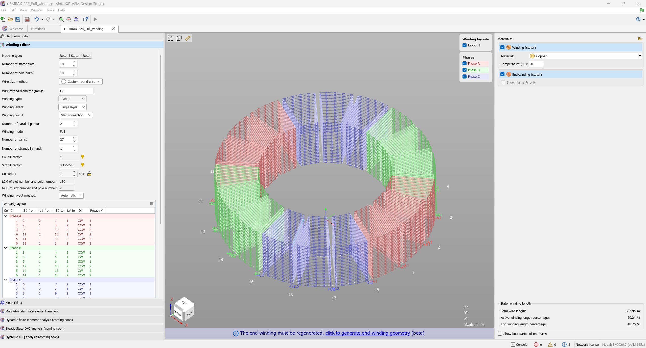
Figure 1. Winding Editor in MotorXP-AFM 2.0.
Winding Editor workspace #
The editor is divided into three main areas:
| Area | Purpose |
| Winding settings | Defines the conductor, winding circuit, number of parallel paths, turns, strands in hand, fill factors, coil span, and winding layout. |
| 3D winding view | Displays the coil arrangement by phase and parallel path. Layout and phase checkboxes can be used to show or hide selected conductors. |
| Materials and results | Sets the winding material and temperature and displays winding-length information. The end winding can be shown as 3D geometry or as filaments only. |
Parameters shared with Geometry Editor #
The machine type, number of stator slots, number of pole pairs, winding type, winding layers, and winding-layer orientation are shared with the Geometry Editor.
Winding type can be Planar or Toroidal. It is selected in the Geometry Editor and is shown in the Winding Editor for reference. Change this parameter in the Geometry Editor when a different winding construction is required.
Typical workflow #
- Define the machine geometry and winding type in the Geometry Editor.
- Select the wire size method and specify the conductor dimensions.
- Choose the winding layers, circuit, number of parallel paths, turns, and strands in hand.
- Create the coil arrangement using the Automatic layout method or edit it manually.
- Review the phase colors, coil directions, and parallel-path numbers in the 3D winding view.
- Configure and generate the end-winding geometry.
- Check the winding material, temperature, phase resistance, end-winding inductance, and winding lengths before running an analysis.
Tip. If the geometry or winding parameters are changed, regenerate the end-winding geometry before reviewing the final 3D model and winding lengths.
Related Winding Editor topics #
- Wire Size Method and Conductor Dimensions
- Winding Layers, Circuit, and Parallel Paths
- Turns, Strands in Hand, and Fill Factors
- Automatic and Manual Winding Layouts
- Understanding the Winding Layout Table
- End-Winding Geometry
- Winding Materials and Output Parameters


