Level. Beginner ★☆☆
This article shows, step by step, how to build a model of the EMRAX 228 axial-flux motor in MotorXP-AFM 2.0 and run a magnetostatic finite element analysis (FEA). The reference data for the machine is taken from the manufacturer’s page: EMRAX 228.
Building the stator model #
The EMRAX 228 has a double-rotor, single-stator axial-flux topology, so the machine type is set to Rotor | Stator | Rotor (RSR). The stator parameters are listed in Table 1, and the process of building the stator model in MotorXP-AFM DS 2.0 is shown in Figure 1.
Table 1. Stator parameters.
| Parameter | Value |
|---|---|
| Machine type | Rotor | Stator | Rotor |
| Stator dimensions | |
| Outer diameter (mm) | 207 |
| Inner diameter (mm) | 129 |
| Number of slots | 18 |
| Stator height (mm) | 55.6 |
| Stator type | Yokeless |
| Winding type | Planar |
| Winding layers | Single layer |
| Stator geometry script — Parallel flat slot | |
| Slot width (mm) | 10 |
| Tooth outer diameter (mm) | 207 |
| Tooth inner diameter (mm) | 129 |
| Tooth fillet radius (mm) | 0 |
| Tooth edge chamfer radius (mm) | 0 |
| Tooth tip height (mm) | 0 |
| Tooth inner border | Curved |
| Tooth outer border | Curved |
| Coreless tooth | Off |
| Coil geometry | Lumped |
| Insulation | |
| Slot insulation thickness (mm) | 0 |
| Between layers insulation thickness (mm) | 0 |
| Wedge thickness (mm) | 0 |
click on image to enlarge
Figure 1. Setting up the stator model.
Building the rotor model #
The rotor parameters are listed in Table 2, and the process of building the rotor model in MotorXP-AFM DS 2.0 is shown in Figure 2.
Table 2. Rotor parameters.
| Parameter | Value |
|---|---|
| Rotor dimensions | |
| Outer diameter (mm) | 207 |
| Inner diameter (mm) | 129 |
| Number of pole pairs | 10 |
| Top rotor height (mm) | 11.4 |
| Bottom rotor height (mm) | 11.4 |
| Rotor type | Yoke |
| Pole arrangement | N-S |
| Top rotor angular displacement (degrees) | 0 |
| Bottom rotor angular displacement (degrees) | 0 |
| Rotor geometry script — Trapezoidal magnet | |
| Magnet outer diameter (mm) | 207 |
| Magnet inner diameter (mm) | 129 |
| Magnet spacing type | Radial |
| Magnet spacing (el.deg.) | 40 |
| Magnet height (mm) | 5 |
| Yoke height (mm) | 6.4 |
| Magnet inset depth (mm) | 0 |
| Number of magnet segments in radial direction | 4 |
| Magnet inner border | Curved |
| Magnet outer border | Curved |
click on image to enlarge
Figure 2. Setting up the rotor model.
Assigning the materials #
Assign a material to each part of the model.
Table 3. Materials.
| Part | Material | Settings |
|---|---|---|
| Iron (stator) | M-19 29 Ga (Maxwell iron loss coef) | Stacking factor 0.95 |
| Winding (stator) | Copper | Temperature 20 °C |
| Iron (rotor) | M-19 29 Ga (Maxwell iron loss coef) | Stacking factor 1 |
| Magnet (rotor) | N40SH | Temperature 20 °C, Segments 4 |
click on image to enlarge
Figure 3. Assigning the materials.
Winding Editor #
Define the winding layout in the Winding Editor. The winding parameters are listed in Table 4. In this example the Wire size method is changed from AWG to Fill factor, and the 3D end-turns are then generated. The process is shown in Figure 4.
Table 4. Winding parameters.
| Parameter | Value |
|---|---|
| Machine type | Rotor | Stator | Rotor |
| Number of stator slots | 18 |
| Number of pole pairs | 10 |
| Wire size method | Fill factor |
| Wire strand diameter (mm) | 11.1304181 |
| Winding type | Planar |
| Winding layers | Double layer |
| Winding layers orientation | Left/Right |
| Winding circuit | Star connection |
| Number of parallel paths | 1 |
| Winding model | Lumped |
| Number of turns | 1 |
| Number of strands in hand | 1 |
| Coil fill factor | 0.35 |
| Slot fill factor | 0.35 |
| Coil span (slot) | 1 |
| LCM of slot number and pole number | 180 |
| GCD of slot number and pole number | 2 |
| Winding layout method | Automatic |
click on image to enlarge
Figure 4. Configuring the winding in the Winding Editor.
Mesh Editor #
Set up the finite-element mesh in the Mesh Editor. The mesh parameters are listed in Table 5. In this example the Maximum triangle side is changed from 10 to 6 mm to refine the mesh. The process is shown in Figure 5.
Table 5. Mesh parameters.
| Parameter | Value |
|---|---|
| Number of axial slices | 3 |
| Boundary conditions | Periodic (Auto) |
| Maximum triangle side (mm) | 6 |
| Minimum triangle angle (°) | 10 |
| Deflection of curve (mm) | 0.05 |
| Air gap mesh | |
| Number of layers in air gap | 3 |
| Air gap mesh quality | Medium |
click on image to enlarge
Figure 5. Setting up the mesh in the Mesh Editor.
Magnetostatic FEA #
Switch to the Magnetostatic finite element analysis tab and set up the calculation parameters.
Table 6. Magnetostatic FEA parameters.
| Parameter | Value |
|---|---|
| Solver type | Nonlinear |
| Convergence tolerance | 0.001 |
| Simulation time period | One electrical period (0 – 0.006 sec) |
| Simulation setup | 4 points per cogging — medium accuracy |
| Number of points | 72 (time step 0.0000833 sec) |
| Advance angle (el.deg.) | 0 |
| Mechanical speed (RPM) | 1000 |
| Compute cogging torque | Off |
| Save each field solution in folder | Off |
| Drive settings | |
| Current waveform | Sinusoidal |
| Current input method | RMS supply current |
| RMS supply current (A) | 0 |
When the parameters are set, click the Run analysis button, save the project file and wait until the calculation is complete.
click on image to enlarge
Figure 6. Magnetostatic finite element analysis.
Results #
The assembled EMRAX 228 model can be inspected in the 3D scene.
click on image to enlarge
Figure 7. The assembled EMRAX 228 model in the 3D scene.
The magnetostatic FEA produces the magnetic field distribution across the model.
click on image to enlarge
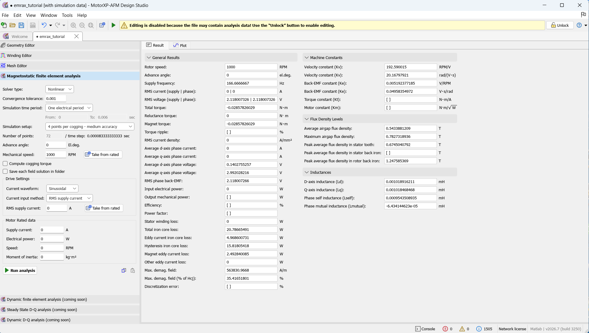
Figure 8. Magnetostatic FEA result.
Example file #
The ready-made project used in this tutorial is available for download:
Thank you for reading.


